
|
|
In the wind turbine independent pitch system courseware, the independent pitch system is introduced. In this section, the drive rod unified pitch drive mechanism is introduced. This pitch mechanism has a wide range of applications in current wind turbines. Introduce its structure and working principle. Figure 1 is a schematic diagram of the structure of the pitch bearing (both figures show the inner and outer sides respectively), the outer ring of the pitch bearing is fixed on the hub (fixed screw holes are not shown in the figure), to dye the difference in yellow, the outer ring of the pitch bearing is cut away. There are a plurality of steel balls between the inner ring and the outer ring of the pitch bearing, and outer ring and inner ring form rolling bearing. Here, the inner ring of the pitch bearing is integrated with the flange of the blade, and the blade mounting flange can be freely rotated in the outer ring of the pitch bearing. The pitch bearing is designed with four-point contact ball bearings and can withstand loads in multiple directions. |
|
| Figure 1--Variable Pitch main bearing and blade mounting flange | |
| The blades of the wind turbine are very long, for a simple display of the deflection angle. The section of the middle section of the blade represents the entire blade, and the blade is mounted on the blade mounting flange by bolts at the root of the blade (the blade is directly placed on the flange in the figure) The flange is also the inner ring of the pitch bearing. There is a pitching handle on the flange, and the handle can be rotated to rotate the blade mounting flange and drive the blades to rotate synchronously. The left diagram of figure 2 is the position where the pitch angle is 0, and the right diagram of figure 2 is the position where the pitch angle is 90 degrees. | |
 |
|
| Figure 2 - Variable pitch bearings and blades | |
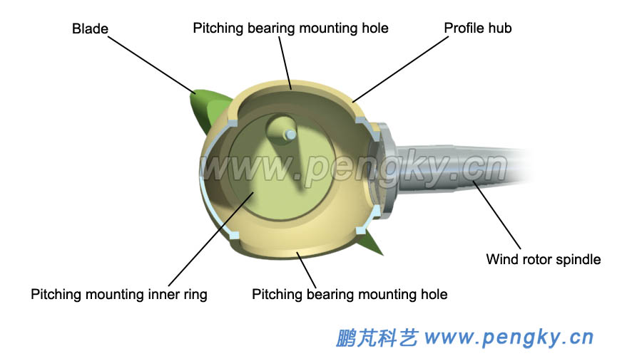
Figure 3 is a schematic illustration of the installation of a pitch bearing on a wind turbine hub. |
|
 |
|
| Figure 3 - Variable pitch bearing and hub | |
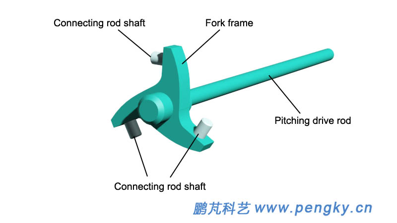
| The pitch drive rod is the main drive component in this mechanism. It consists of a straight shaft and a fork. The plane of the fork is perpendicular to the shaft. The fork has three arms (for three-blade). There is a link rod shaft at the end of the arm for connecting the link rod, see figure 4. | |
 |
|
| Figure 4--Pitch drive rod | |
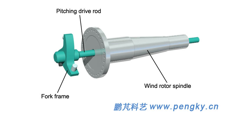
| One end of the fork of the pitch drive rod is located in the hub, and the shaft passes through the main shaft of the wind rotor through the extension rod and then passes through the low speed shaft through hole of the gear box to connect the pitch drive. The drive is composed of hydraulic device or electric device, and is driven by the drive. The pitch drive rod can slide in the through hole of the main bearing of the wind rotor, and the fork frame can extend or retract, as shown in figure 5. | |
 |
|
| Figure 5 - Pitch drive rod and wind rotor spindle | |
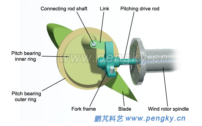
| In figure 6, a pitching device for a blade is shown. The two ends of a connecting rod are connected to the connecting rod shaft on the fork frame arm and the connecting rod shaft (shank shaft) on the pitch shaft seat when the pitch is driven. When the rod moves in the through hole of the wind turbine main shaft, it can drive the inner ring of the pitch bearing (blade mounting flange) to rotate. | |
 |
|
| Figure 6 - Pitch drive mechanism of a blade | |
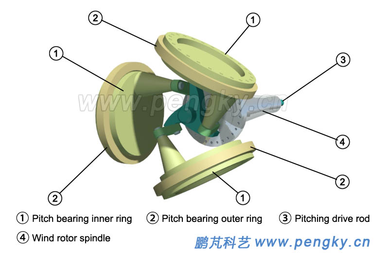
| Figure 7 is a diagram of a mechanism with three pitch bearings, with the hub and blades not shown. | |
 |
|
| Figure 7 - Pitch drive mechanism of three blades | |
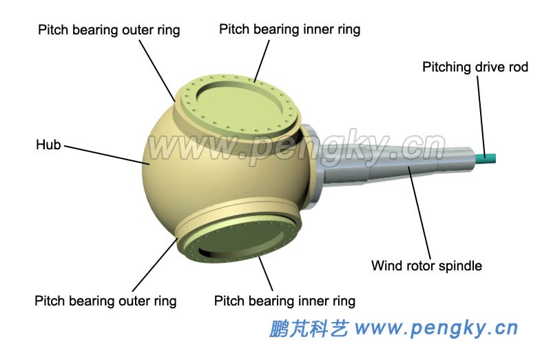
| Figure 8 is a perspective view of a hub equipped with three blades pitch bearings (flanges). | |
 |
|
| Figure 8 - Variable ptich hub | |
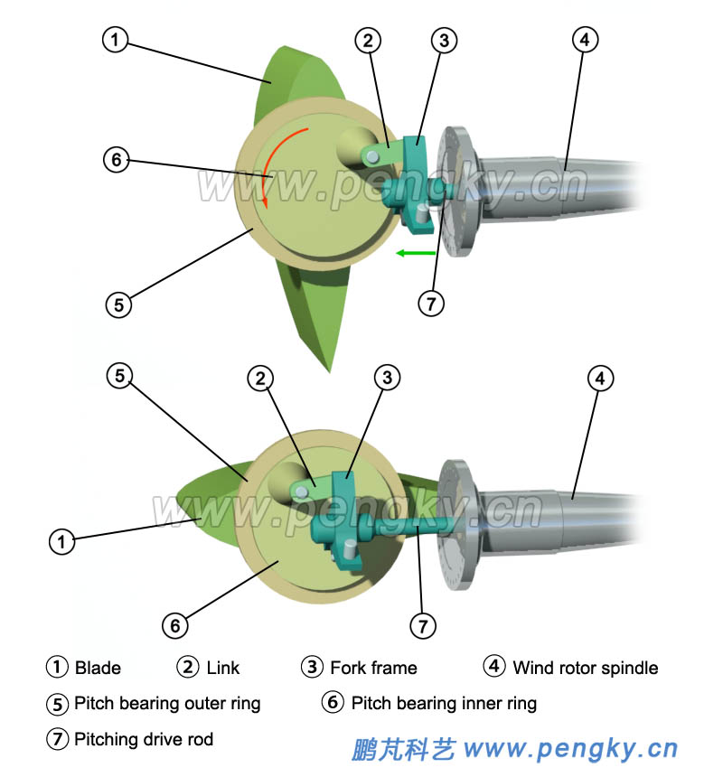
The following two pictures are used to indicate the angle of the pitch bearing inner ring (blade flange) and the blade when the pitch drive rod is in different positions. For the sake of simplicity and clarity, only one set of pitch blades is shown in figure 9 The figure above shows the angle between the blade flange and the blade when the variable pitch drive lever is retracted. The blade pitch angle is 0; when the variable pitch drive rod is extended (the green arrow line indicates the direction), the blade flange rotates (the red arrow line indicates the rotation) Direction), the pitch angle increases; the figure below shows the blade flange and blade angle when the variable pitch drive rod reaches the end position, and the blade enters the full feather state. |
|
 |
|
| Figure 9 - Principle of the drive rod variable pitch drive mechanism | |
In addition,the connection and control changes of the other two sets of blade flanges are the same as those of the first set of variable pitch mechanisms. When the variable pitch drive rod moves, the blade flanges of the three groups rotate synchronously, that is, the variable pitch angles of the three blades change synchronously, so called the unified pitch drive mechanism, also known as synchronous variable pitch drive mechanism. This variable pitching process will be demonstrated in the animation below. |
| Back to Previous Page |

