
| Toothed Belt Pitch System |
Toothed belt pitching technology is widely applied in various serious of wind turbine of GOLDWIND Toothed belt such as synchronous toothed belt, synchronous belt is similar to common V-belt and flat belt in driving type, as a flexible transmission form. A tooth shape is formed on the inner circumference of the belt to mesh with the toothed belt gear. On account of being made of steel wire rope or fiber rope as the strong layer, and covering with polyurethane and neoprene material, therefore, it will not stretch and deform easily, and because of the teeth, it will not slip, ensuring synchronous transmission and constant transmission ratio. The figure 1 is showing a toothed belt wound two cylinders. |
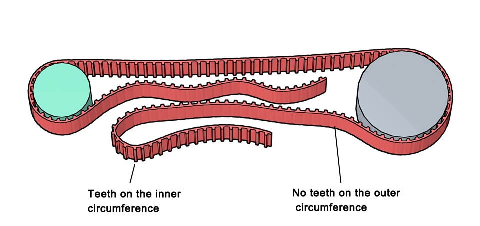 |
| Figure 1—Toothed belt |
| 1. The principle of toothed belt pitching |
Figure 2 is the principle diagram of the toothed belt pitching system, the inner ring of pith bearing is fixed on the hub, and the wind turbine blade is installed on the pitch bearing outer ring. The toothed belt bypasses the pitch driving gear and tension wheels, furthermore both ends are fixed on the outer surface of the outer ring of the pitch bearing with toothed belt pressure plates. The toothed belt is wound on the outer surface of the outer ring of the pitch bearing, and when the pitch driving gear rotates, it drives the outer ring of the pitch bearing to rotate. Like the gear rodent driving type, the toothed belt pitching technology is an independent pitching technology. The tip section of the blade in figure 2 shows the angle of the blade at this time (schematic), the left drawing in the figure 2 is the angle of the blade with working normally position, and the right drawing is the angle of the blade stop working position. |
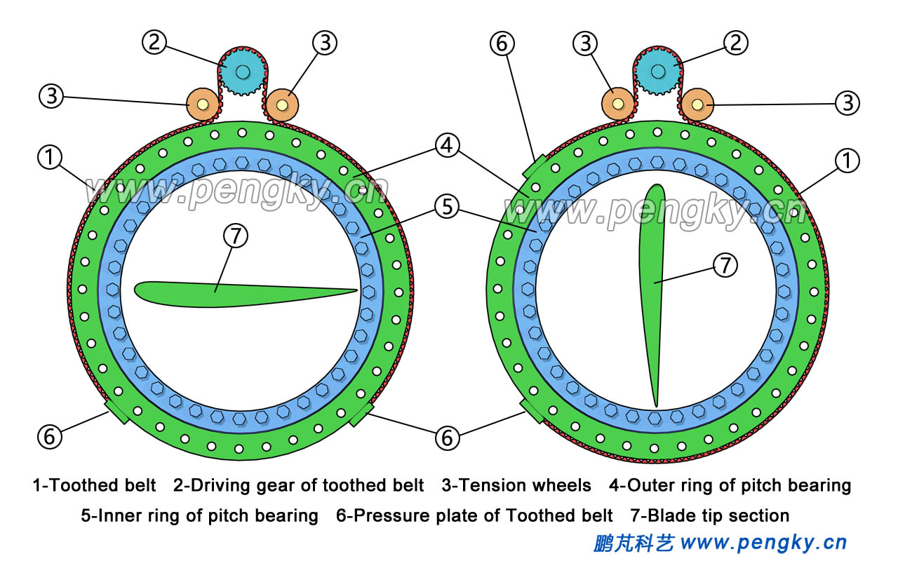
| Figure 2—Toothed belt pitching principle schematic diagram |
The following is an animation vide of toothed belt pitching working principle |
| Animation-working principle of toothed belt drive pitch |
| 2. Toothed belt pitching mechanical structure |
Figure 3 is mechanical principle schematic of toothed belt pitching in wind turbine, the toothed belt driving pitch system is installed on the three-way hub, being installing with pitch bearings of blade. The inner ring of the pitch bearing is fixed on the hub with bolts, and the outer ring of the pitch bearing will be installed with blade. The bracket of the pitch driving unit is installed on the hub, next to the pitch bearing. The pitch driving gear, tension wheel, and pitch motor are installed on the driver bracket. |
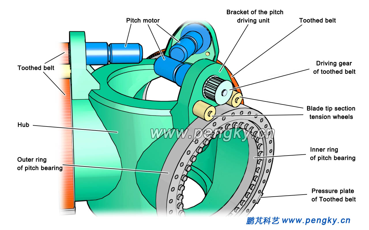
| Figure 3—Structure of toothed belt pitch system (1) |
Pitch motor has the same structure as the yaw motor. It mainly includes a drive motor and a reduction gear box, as well as a breaker inside. The output shaft of the motor is equipped with a pitch driving gear. The toothed belt bypasses the drive gear and passes through the tension wheel, meshing closely with the driving gear, and both ends of the toothed belt are fixed on the outer surface of the outer ring of the pitch bearing under the action of toothed belt pressure plates with adjustment function. Two tensioning wheels make the toothed belt tightly wrap around the driving gear to ensure that the driving gear tightly drives the outer ring of the pitch bearing to rotate smoothly, as shown in figure 4 below. |
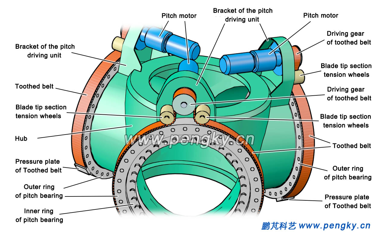
| Figure 4—Driving structure of toothed belt pitch system(2) |
Figure 5 is a view of the hub with 3 sets of toothed belt drive pitch devices installed. |
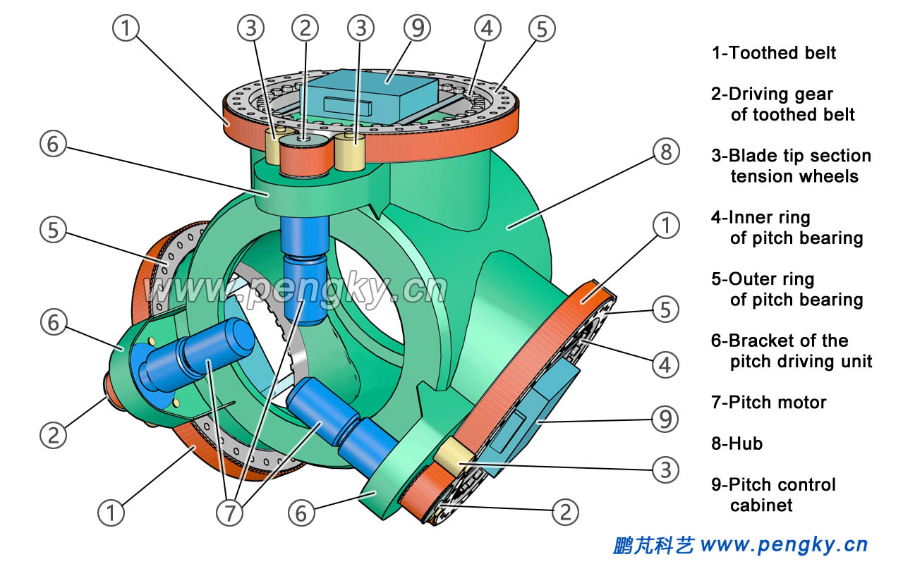
| Figure 5—Hubinstalledwithtoothedbeltpitchsystem |
There is also a hood to protect the pitch drive gear and the tension wheel on the pitch drive bracket. A pitch control cabinet is installed inside each pitch bearing. |
| 3. Pitch control cabinet |
Three pitch control cabinets are also installed in the hub, and each control cabinet individually controls and drives each blade. In the pitch control cabinet, there are mainly power supply systems, pitch controllers, and pitch inverters. The power supply system converts AC power into DC power of two voltages and supplies it to the pitch inverter and the pitch controller. The pitch controller sends a command to the pitch inverter according to the pitch command of the main controller of the wind turbine to control the rotation of the pitch motor.
The pitch controller collects the signal when the blade pitch angle reaches 0 degree position and the signal when the blade pitch angle reaches 90 degree, and the blade operation state to send the brake control signal to the pitch motor. The pitch controller also sends a cooling fan (motor heat dissipation) control signal or heater working signal to the pitch motor based on the motor temperature information. The pitch motor adopts a three-phase asynchronous motor, and the motor speed is determined by the frequency of the alternating current emitted by the pitch inverter. For debugging and maintenance needs, the pitch control cabinet is also equipped with a manual pitch operation knob. Since the hub is working in a rotating state, both the pitch system supply power and control signal are transmitted to the pitch control cabinet through the slip ring from nacelle. In the power supply system of the pitch control cabinet, there is a storage device with a certain capacity as a backup power supply. When the system power supply fails or the slip ring fails, the pitch controller relies on the backup power supply to turn the blades into the stop position. Ultra capacitor is suitable to be as backup power with the advantages of short charging time and long life. Figure 6 is the block diagram of pitch control system. |
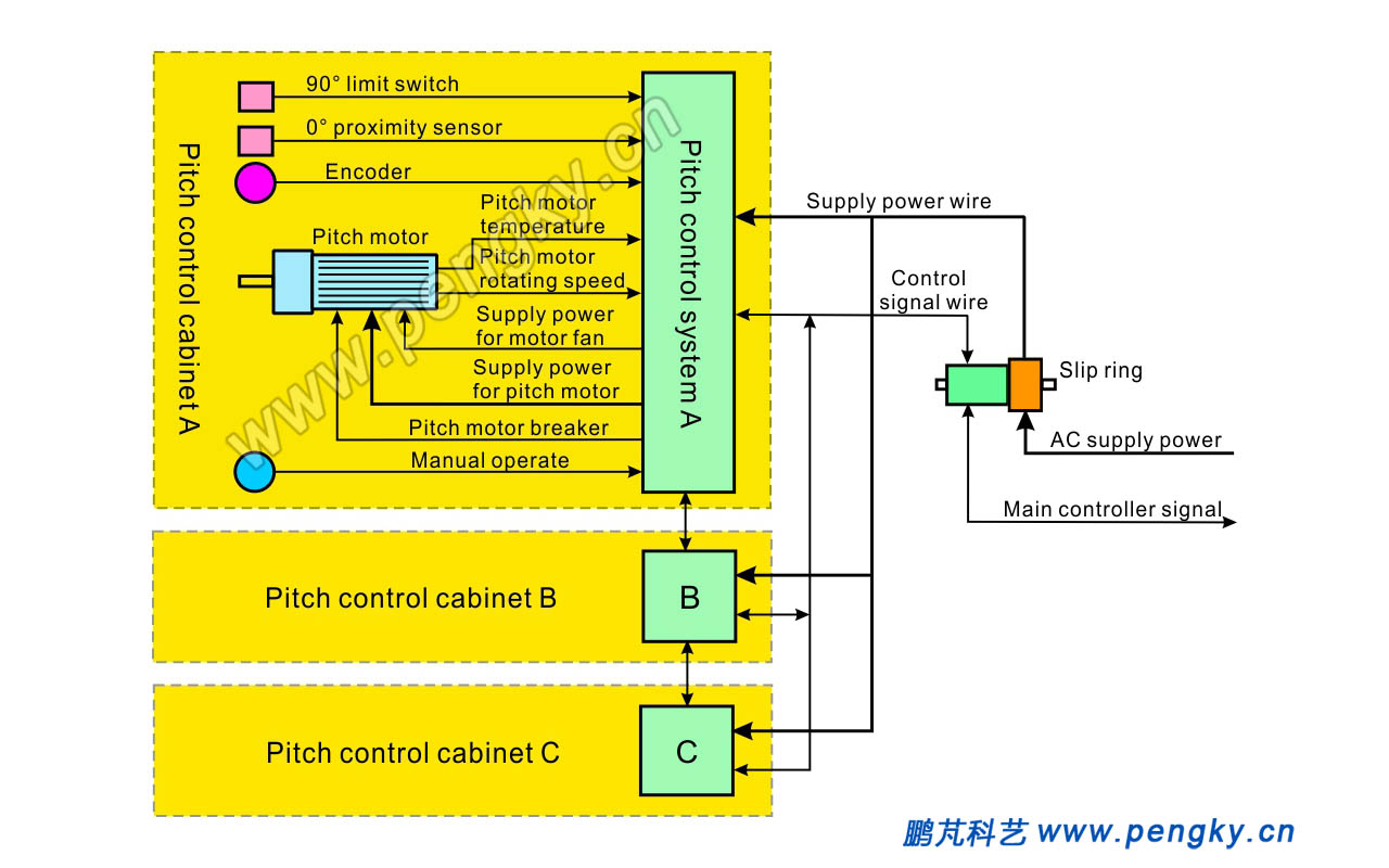
| Figure 6-- Pitch control system block diagram |
4. Other structure of toothed belt pitch system |
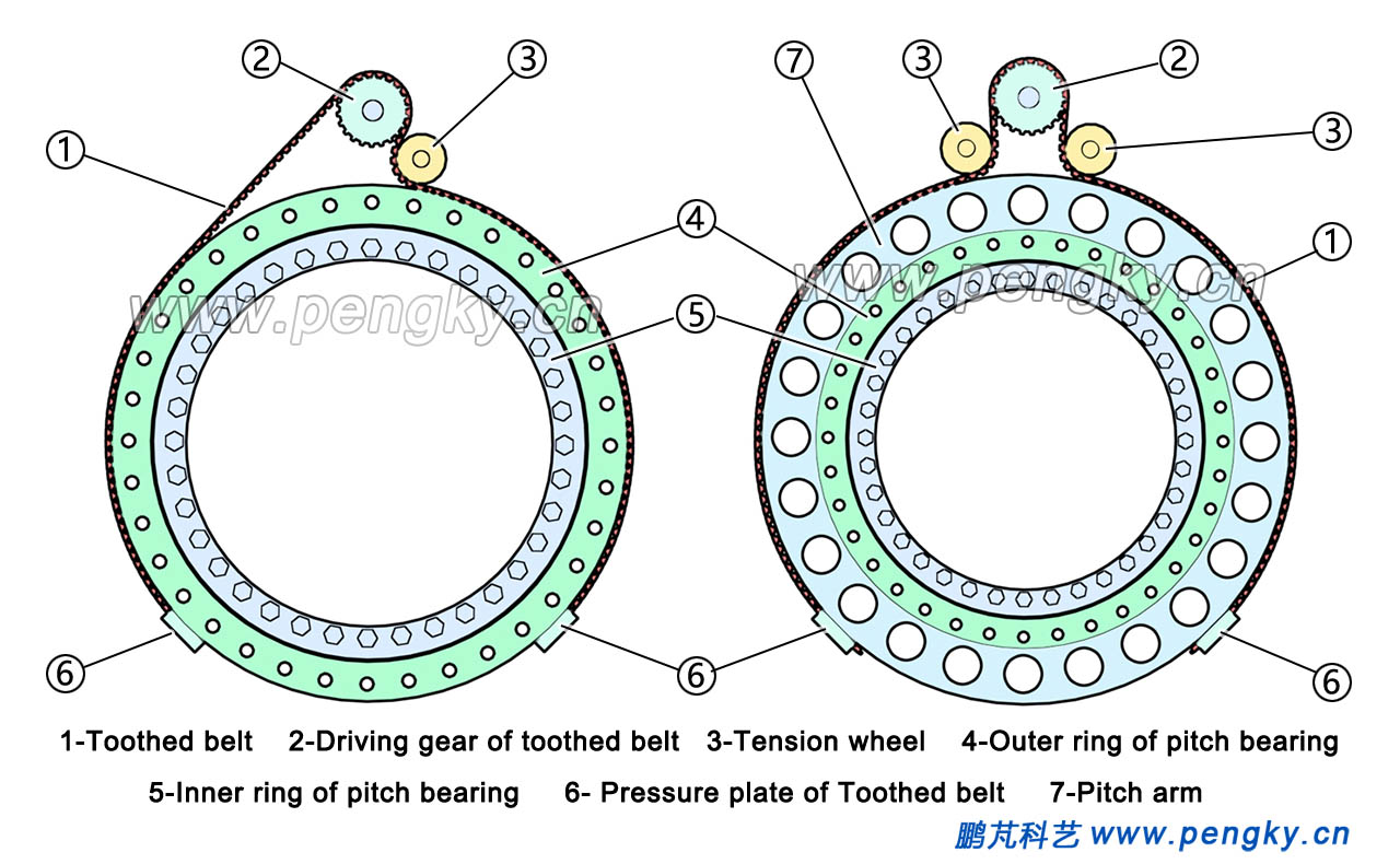
The toothed belt pitch system mainly has three structures. Figure 7 shows the other two structures. The photograph on the left is a structure with only one tensioner. The photograph on the right shows a circle of pitch disc added to the outer ring of the pitch bearing. When the diameter of the pitch bearing is smaller, the pitch disc increases the pitch arm, which makes the pitch drive easy and stable. |
| Figure 7-- Other structure of toothed belt pitch system | ||
The main advantages of toothed belt drive pitch system are uniformity, stability, easy replacement and maintenance, unlike mechanical gear driving structure that often need to lubricate grease. |
||
| Back to Previous Page | ||
