
| Wind Rotor Solidity | |
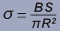
The concept of wind rotor solidity is described in the section "Basic knowledge of wind turbine": the ratio of the total area of the wind turbine blades (projected in the wind direction) to the area of the wind passing the wind rotor(sweeping area of the wind turbine) is called the solidity (solid ratio, volume ratio) is a reference data for wind turbine. Figure 1 is a schematic diagram of several horizontal axis wind turbine rotor with four kinds of rotors of single blade, double blades, three blades and multiple blades. S is the projected area of each blade to the wind direction. R is the radius of the wind rotor. B is number of blades. And σ is the solidity ratio. |
|
 |
|
| In figure 1, the solid ratio of the wind rotor from single blade to three blades is small, which is a low solid wind rotor. And the rotor has a high solidity ratio of 12 blades, which is a high solid wind rotor. | |
 |
|
| Figure 1 - Single blade to multi blades wind rotor solidity | |
| At present, the wind rotors of most horizontal axis wind turbines are in the form of three blades. A video from the network shows the structure of this wind turbine wind rotor. | |
| Three-blade wind turbine video | |
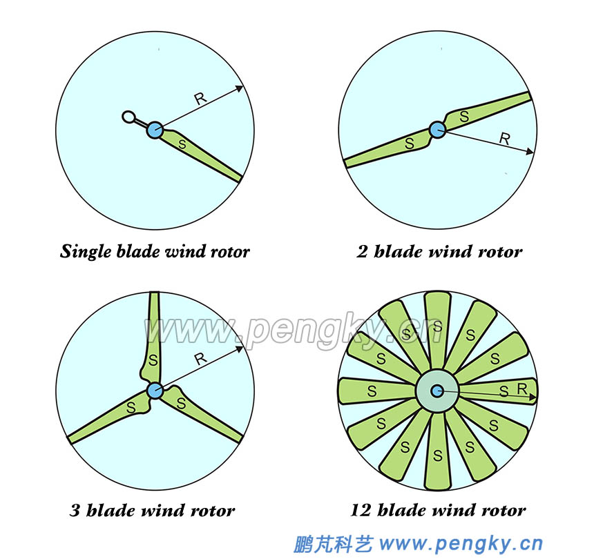
| There are also some agricultural pumping wind turbines and some small micro wind turbines in the form of multi-blade, see figure 2. | |
 |
|
| Figure 2 - Wind turbine with multi-blade wind rotor | |
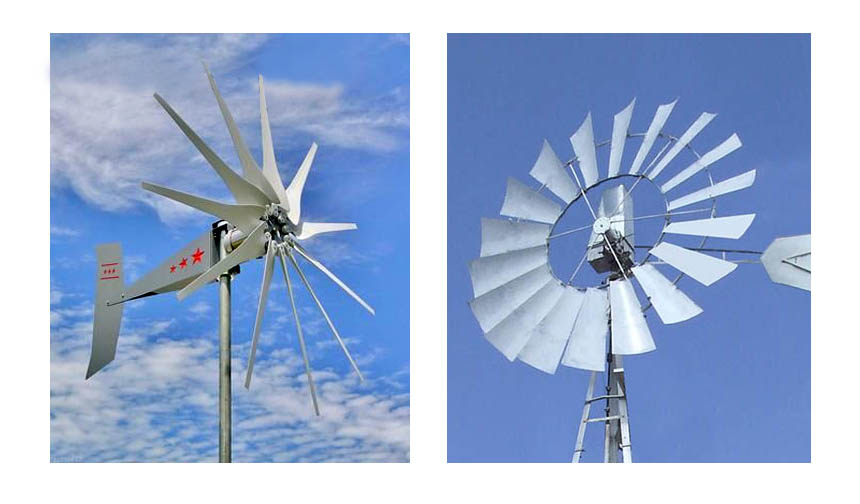
Some people who are new to wind turbine often question that three thin blades have caused most of the wind to leak, so why not use multi-blade wind rotor to accept more wind energy. Some people also design some high-solidity wind turbine, Even front and rear two-stage high-solidity wind turbines. They are considered to be wind turbines with high wind energy utilization. In fact, high-solidity wind rotor may not improve wind energy utilization. The result may be opposite. We will make a simple explanation through figure 3: the upper part of the figure is a schematic diagram of the airflow through the ordinary three-blade (low-solidity) wind rotor. After the airflow passes through the blade rotor, the speed is slowed down, and the airflow diverges around because of the slower speed. There is a flow curve for the gas divergence shown in the figure. |
|
 |
|
| Figure 3 - Schematic diagram of three-blade and multi-blade airflow | |
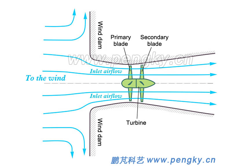
The lower part of figure 3 is a schematic diagram of the air flow through the multi-blade (high-solid) wind rotor. The multi-blade greatly increases the resistance of the gas passage. A part of the air flow will bypass the blade rotor flow to the rear. This part of the air flow does not work through the blade rotor, so the actual wind energy obtained by the blade rotor is reduced, which is an important reason why multi-blade the wind turbine can't get more wind energy. Can you not let the airflow bypass the blade rotor? Only the wind around the wind rotor is blocked (figure 4). A wind dam is set up. The wind dam has an airflow passage. The wind rotor is installed in the airflow passage so that the airflow will not bypass the wind rotor, the wind dam causes a large pressure difference between the front of the dam and the back of the dam. The rear section of the channel diffuses so that the airflow velocity in the inlet channel is much higher than the original wind speed, which is enough to promote the high speed of the rotor rotation. If the wind dam is large enough, you can add one more wind rotor blade to improve the wind energy utilization. If the wind speed and wind rotor area are only taken from the wind dam, the wind energy utilization rate must exceed the Bates limit. In fact, the area of the entire wind dam should be regarded as the wind receiving area, so that the wind energy utilization rate is small, and the establishment of wind dams will greatly increase the cost and have no practical application value. Unless there are ready-made objects or buildings acting as wind dams, since such wind dams will not rotate with the wind direction, they can only be applied to places where the wind direction is stable for a long time. |
|
 |
|
| Figure 4 - Schematic diagram of the wind turbine in the air duct | |
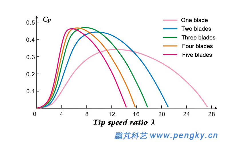
Installing the diffuser on the outer circumference of the wind rotor can increase the wind speed in the diffuser and increase the solidity of the wind rotor. For the application of the diffuser, see the section on the diffused amplifier wind turbine. Is the low-solid blade wind rotor missing most of the airflow? If the wind rotor does not rotate, the blade is stationary, and most of the airflow does leak, but the situation is different when the wind rotor rotates at high speed. The low-solid wind turbine has a higher running speed, the blade linear velocity is many times higher than the wind speed, and has a high tip speed ratio. During the time when the airflow passes through the thickness of the blade rotor, the blade rotor rotates at a large angle, All the blades sweep through most of the airflow through the blade rotor, that is to say through the majority of the airflow of the blade rotor, works on the blade rotor, so that the wind rotor with low solidity and less blades can obtain more wind energy when rotating at high speed. The wind rotor with too high solidity not only hinders the passage of the airflow, but also the wake of the rotating blades also causes the mutual influence between the blades, and the problem of the stalling of the blades will reduce the efficiency of the wind turbine. How many blades are selected is suitable, and a lot of experiments have been done at domestic and abroad. Figure 5 is a curve of wind energy utilization coefficient from a single blade to a five blades horizontal axis wind turbine. The abscissa is the tip speed ratio, and the tip speed ratio is the ratio of the tip speed of the wind rotor blade tip to the wind speed before the wind rotor; the ordinate is the wind energy utilization coefficient (power coefficient), the wind energy utilization coefficient is the ratio of the power obtained by the wind turbine to the wind power passing through the swept area of the wind turbine blade.. |
|
 |
|
| Figure 5 - Wind energy utilization coefficient curve from single-blade to five-blades | |
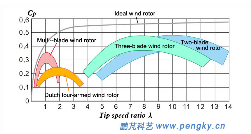
From the wind energy utilization coefficient curve, it is seen that from five-blades to three-blades have higher maximum wind energy utilization coefficient, but five-blades and four-blades have smaller tip speed ratio range when the maximum wind energy utilization coefficient is used (the range of wind speed variation is smaller) .Since wind turbines want high speed of the wind rotor (which can reduce the gearbox's speed-increasing ratio), high wind energy utilization coefficient can be obtained in a wide range of wind speeds, that is, to have a wider tip speed ratio. For the range work, there are still high wind energy utilization coefficient when using 3, 4, and 2 blades running at high tip speed ratio. The low-solid wind rotor has fewer blades, and the blade is narrower than the multi-blade high-solid wind rotor. Therefore, the low-solid wind rotor is used, and the high-speed ratio operation is the choice of the wind turbine generator, that is, the three, two, and four blades are the common choices for wind turbines. The three blades are mostly used. This is the structure of "one pole and three needles". Of course, the choice of three blades also has other reasons such as the structural strength and appearance of the wind turbine. The multi-blade wind rotor has a large degree of solidity and a relatively low utilization rate of wind energy. In figure 6 left, the wind energy utilization coefficient curve of the multi-blade wind rotor (high-solidity wind rotor) is indicated, and its tip speed ratio range is also small (no more than 2). However, the multi-blade wind rotor also has advantages. The multi-blade wind rotor with the same diameter has a much larger output torque than the small blade wind rotor at the same wind speed, and the low wind speed starting ability is very strong, so it is used more in rural pumping and milling. In areas with stable wind speeds, especially in low wind speeds, wind turbines with 4 to 8 blades are likely to achieve better wind energy utilization depending on the application. Multi-blade wind turbines are generally only used in fixed-blade wind turbines, and for variable-blade wind turbines, it is necessary to consider increasing the cost of the blades. |
|
 |
|
|
|
The above is a brief introduction to the basic common sense of the wind rotor solidity and wind energy utilization coefficient. The actual situation is more complicated. The wind rotor with the same number of blades will also have different wind rotor solidity due to different blade chord length (blade width). The angle of attack and shape of the blade directly affect the wind energy utilization coefficient of the wind turbine. Solidity is not only important in horizontal-axis wind turbines, but also in lift-type vertical-axis wind turbines. The vertical-axis wind turbines that actually operate under lift are mostly 2 or 3 blades, and the blades are narrow. The wind rotor solidity is very small. There is also an interesting question: many people who have seen actual wind turbines will ask if the three blades rotate so slowly to generate electricity. In fact, the blades do not rotate slowly, and the tip speed is tens of meters per second. A wind turbine rotor with a diameter of 100m has a circumference of about 314 meters. At normal wind speed, the speed of the wind rotor is about 12 revolutions per minute, and 5 seconds per revolution. At this time, the tip speed is 62.8 meters per second and 226 kilometers per hour. It is much faster than the car on the highway. The speed of the wind rotor cannot be too fast. Too fast requires high blade strength, which will increase the cost; and the blades rotating at high speed will generate great noise. |
|
| Back to Previous Page |
