
|
|
| Lifting force and stall of the blade | |
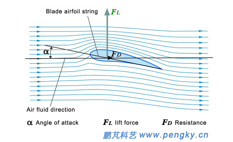
The lifting force and resisting force of the blade is described in the wind turbine basic knowledge section. This course provides further information on the aerodynamic characteristics of the horizontal axis wind turbine blade. Figure 1 is a cross-sectional airflow diagram of a blade in operation. We define it is airfoil. The angle between the airfoil string and the direction of the airflow (angle of attack) is α, During normal operation, the airflow adheres to the airfoil surface, the airflow velocity above the airfoil is faster than the airflow velocity below, according to the Bernoulli principle of fluid mechanics, the airfoil is subjected to product rising force Fl, and the airfoil is also subjected to product resisting force Fd. |
|
 |
|
| Figure 1 – Attack angle of the airfoil | |
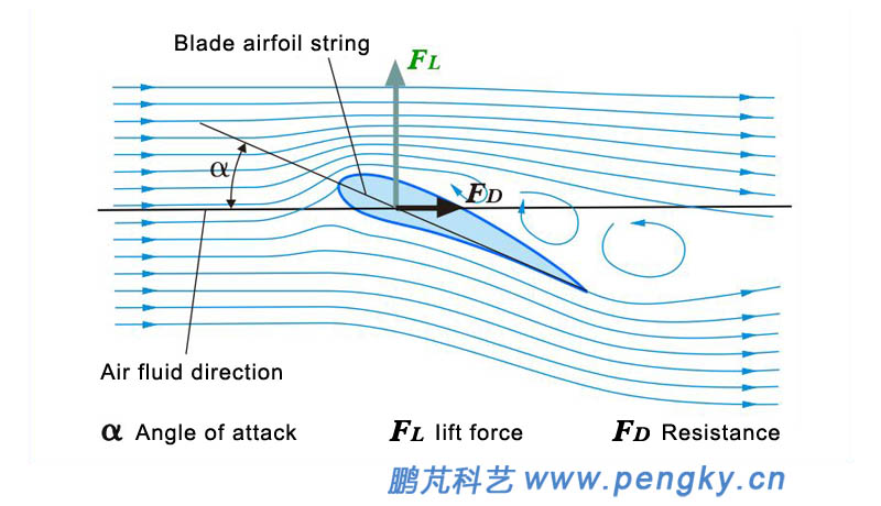
| This is a normal working condition with a large lifting force and little resisting force, but the airfoil does not produce large lifting force in any circumstances. If the angle of attack α is large enough, the air will no longer adhere to the airfoil surface, but the airflow will separate above the airfoil, and vortex will occur behind the leading edge of the airfoil, this will cause the resisting force rising sharply and the lifting force decreasing. This situation is called stall, and the critical angle at which the transition occurs is called the critical angle of attack or the stall angle of attack. As shown in figure 2. | |
 |
|
|
|
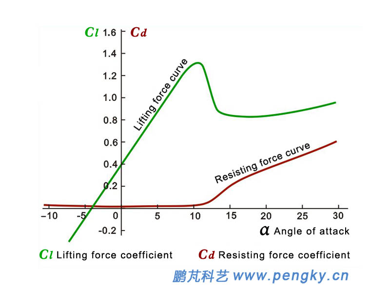
| When dose the airfoil start to stall? Figure 3 is a curve of the lift coefficient and drag coefficient of the airfoil changing with the angle of attack, this is a perfect curve that works in ideal condition. It is close to most thin airfoils. The green curve in the figure 3 is the lift curve and brown curve is the drag curve, it can be seen from the curve in figure 3 that the lifting force increases with the increase of α when the angle of attack α is below 15 degree. When the angle of attack α is greater than 15 degree, the stall will occur, the lifting force suddenly drops, the resistance rises sharply, when α is equal to 45 degree, the lifting force and resisting force are substantially equal | |
 |
|
| Figure 3 - Lift curve and drag curve of the airfoil | |
| The lifting force curve and the resisting force curve of the airfoil above are curves when the airflow is stable and the airfoil angle of attack changes slowly, this stall generated in such condition is called static stall. If the airflow has turbulence and vortex flow, the airfoil angle of attack changes rapidly, the lift curve and the drag curve will change greatly, the stall generated in this condition is called dynamic stall, and the courseware referring to the NACA0012 airfoil has a brief introduction to dynamic stall. For more information on the principles of airfoil lift force and resisting force, see the aerodynamic basic courseware of blade. | |
| Wind turbine airfoil | |
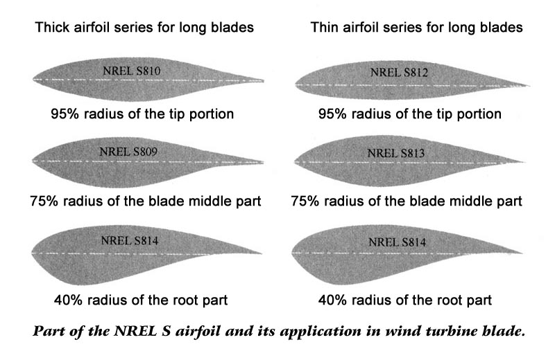
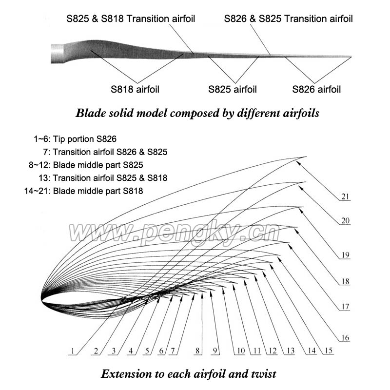
The inchoate wind turbines mostly used the NACA series airfoil, but the wind turbine is a large rotary machine, the blade wing is different from the aircraft wing. To ensure the wind turbine strength, the thickness of the blade near the root is large, but the resistance cannot be too large; The blade requirements are that the maximum lift coefficient is large, the lift-to-drag ratio is high, the aerodynamic performance is stable at the time of stall, and the aerodynamic performance is less sensitive to the rough change of the leading edge surface of the blade. So in the mid-1980s, some countries with developed wind energy technologies developed their own wind turbine-dedicated airfoil series, including the US NREL S airfoil series, the Danish RISO airfoil series, and the Swedish FFA- W wing series, Dutch DU airfoil series, China also developed the WA series. The following is a picture of the book 《Modern Land and Sea Wind Turbine Calculation and Simulation》, as shown in Figure 4. The picture shows the application of the NREL S airfoil in various parts of the wind turbine blade. |
|
 |
|
| Figure 4- Wind turbine dedicated airfoil | |
| Blade structure | |
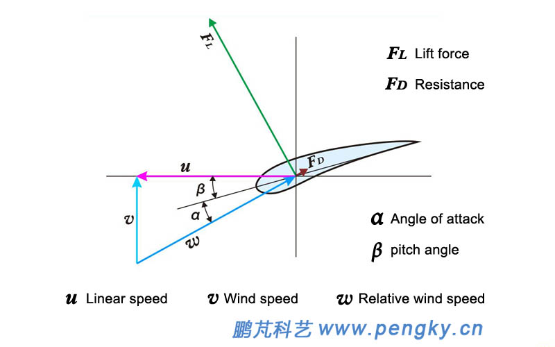
| The airfoil string in Fig. 5 has a fixed angle β with the airfoil advancing direction, which is called the pitch angle. The wind speed of the relative airfoil is the relative wind speed of the external wind speed v and the airfoil linear velocity u. The angle α between the relative wind speed w and the airfoil string is the angle of attack of the airfoil. Try to get the airfoil to work at the angle of attack before stall to get maximum lift and less resistance. For a certain wind speed v and a certain line speed u, the appropriate airfoil pitch angle β is selected to obtain the most suitable angle of attack α. | |
 |
|
| Figure 5- Airfoil pitch angle | |
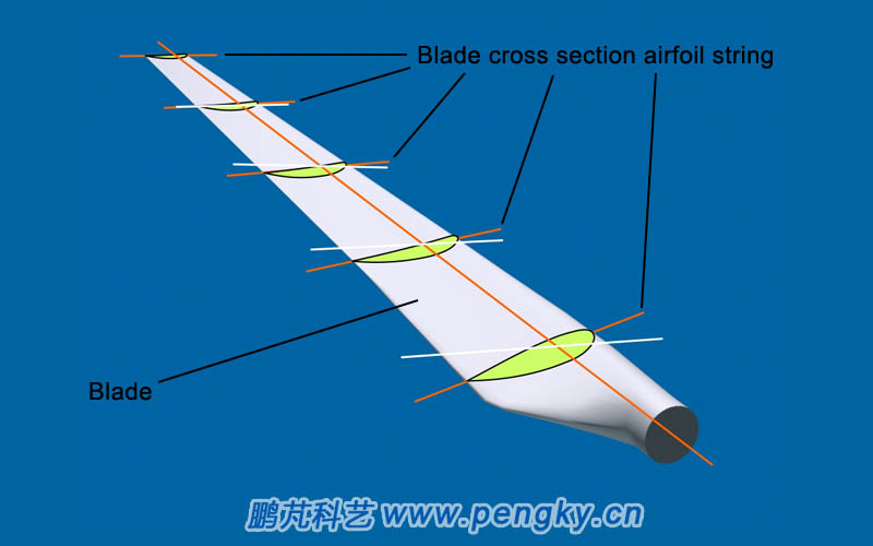
| The actual blade rotates around the axis, and the linear velocity u of different sections along the length of the blade is different, the tip is the fastest, and the root is the slowest. For the same wind speed v, the angle between the relative wind speed and the plane of the wind rotor is the smallest at the tip of the blade, and the angle between the relative wind speed and the plane of the wind rotor is the largest at the blade root. In order to make the blade segments work at a good angle of attack, the blade must be made torsional. Figure 6 is a wind turbine blade with cross section (light green) on each section of the blade. An extension (orange-red) of the cross-section string at each end of each cross section, horizontally with the blade end cross-section string (horizontal line White). It can be seen that the angle between the cross-section strings and the horizontal plane is the largest at the root of the blade. | |
 |
|
| Figure 6- Wind turbine cross section of different part | |
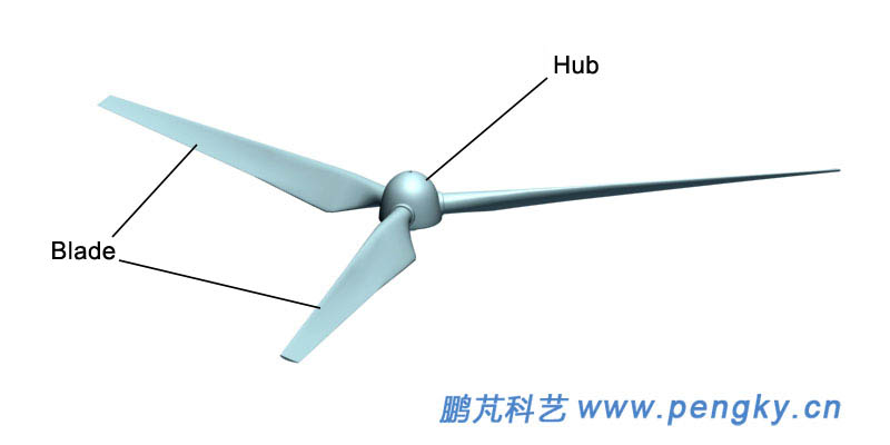
| The installation angle of the blade on the wind rotor is the smallest at the tip of the blade and the rotating plane of the wind rotor, and the angle at the root of the blade is the largest, as shown in Fig. 7. | |
 |
|
| Figure 7- Wind rotor with three blades | |
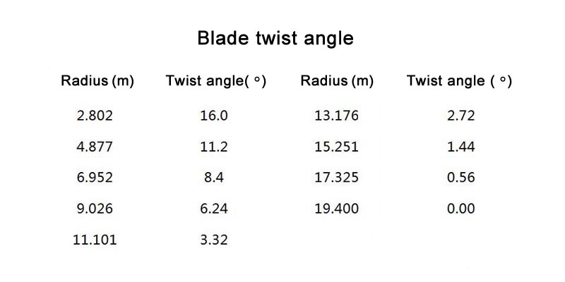
| This twist angle is different for different wind turbines and blades, but there is little difference between large and medium wind turbines. The data in the attached table below is from the book Design, Manufacture and Operation of Wind Turbines. The data in the table is a rotor with a radius of about 40 m and the twist angle of the blades at different radius. This angle is the design optimization value for the optimum operating wind speed of 8 m/s. | |
 |
|
In addition, in the book Modern Large Wind Turbine Design Principles, a picture is scanned for reference. See Figure 8. The cross-sectional view of the certain wind turbine blade at different parts (radius) is shown. The small number is the tip part, the big number is the blade root part. |
|
 |
|
|
|
| Back to Previous Page |
