
Wind Turbine Basics |
|
| Wind energy was once the most important driving force before the vapor engine was invented. Thousands of years ago, there were sailboats used for transportation, and later windmills used to grind and pump water. In recent years, due to the gradual depletion of traditional energy sources and serious environmental pollution, wind energy is valued as a clean new energy source. In order to facilitate the learning of wind turbine technical knowledge, the basic knowledge of wind turbine aerodynamics is introduced below. | |
| Lift force and resistance | |
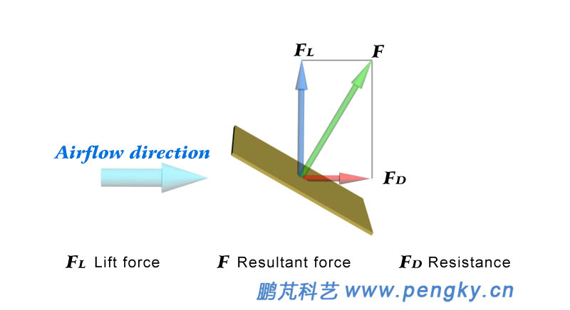
| The wind is the flowing air. A thin flat plate placed in the flowing air will be applied force by the airflow. We break this force into resistance and lift force. In Fig. 1, F is the force applied to the plate, FD is the resistance, and FL is the lift force. The resistance is parallel to the direction of the airflow and the lift force is vertical to the direction of the airflow. | |
 |
|
| Figure 1 - Lift force and resistance diagram | |
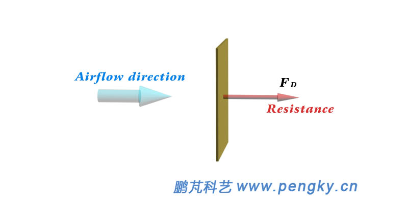
Let us first analyze the situation when the plate is vertical to the direction of the airflow, as shown in Figure 2. At this time, the plate receives the greatest resistance and the lift force is zero. When the plate is stationary, the resistance is large but does not work on the plate; when the plate moves under the resistance, the airflow works on the plate; if the direction of the plate motion is the same as the airflow, the airflow is zero relative to the plate speed, then the resistance is zero, the airflow did not work on the plate. In general, a flat plate subjected to resistance movement can obtain a large power when the velocity is 20% to 50% of the air flow velocity, and the resistance type wind turbine works by utilizing the resistance of the blade. |
|
 |
|
| Figure 2 - Formation of resistance | |
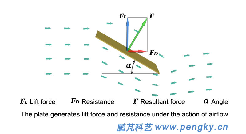
When the plate is parallel to the direction of the airflow, the plate is subjected to zero force (both resistance and lift force are zero). When the plate is at an angle to the direction of the airflow (see Figure 3), the airflow encounters the windward surface of the plate and will turn obliquely downward, thereby giving the plate a pressure. When the airflow bypasses the plate, a low-pressure zone is formed on the leeward side of the plate. The differential pressure produces a lateral force F that can be decomposed into the resistance FD and the lift force FL. |
|
 |
|
| Figure 3 - Formation of lift force and resistance | |
Below is an animation of the lift force and resistance generated by the airflow. |
|
| Animated plate flow to generate lift force and resistance | |
The angle between the thin plate and the direction of the airflow is called the angle of attack. When the angle of attack is small, the resistance FD of the plate is small. At this time, the force applied to the plate is mainly the lift force FL, as shown in Fig. 4. |
|
 |
|
| Figure 4 - Lift force and small resistance at small angles of attack | |
Aircraft and kite can rise to the air by relying on lift force, and lift force-type wind turbine rely on the lift force of the blades. |
|
| Airfoil | |
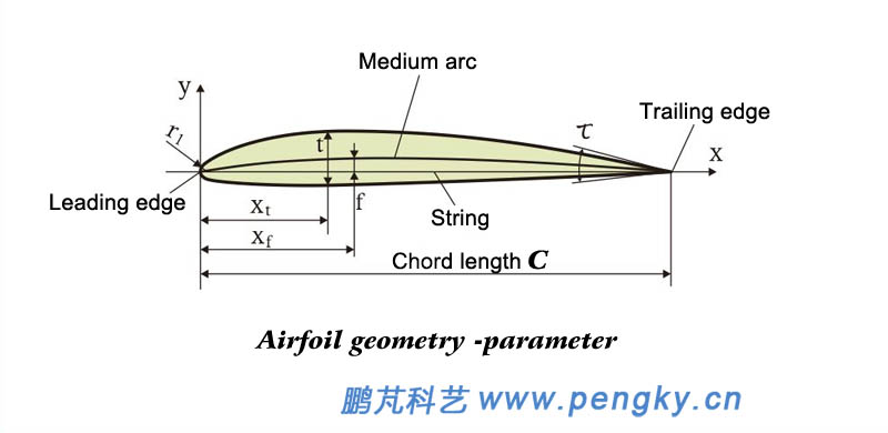
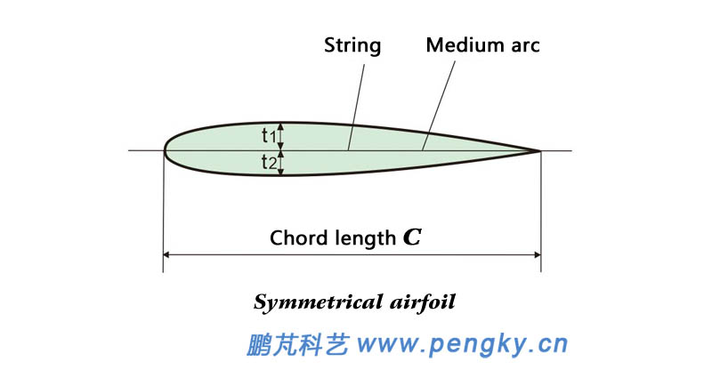
| The airfoil is a term from aviation dynamics. It is the shape of the airfoil section. The airfoil is streamlined pattern. The blades of the wind turbine are airfoil with wings or similar wings. Figure 5 is the geometry -parameter of the airfoil. | |
 |
|
| Figure 5 - Airfoil parameters have medium arc, string, curvature, thickness, etc. | |
| The curve equal to the distance between the upper and lower surfaces of the airfoil is called the mid-arc line, and the airfoil is described by the following parameters: | |
| (1) Leading edge and trailing edge | |
| The foremost point of the arc in the airfoil is called the leading edge of the airfoil, and the last point is called the trailing edge of the airfoil. | |
| (2) String, chord length | |
| The line connecting the leading edge and the trailing edge is called a string; its length is called the chord length and is represented by c. Chord length is important data, and all dimension data on the airfoil is the relative value of the chord length. | |
| (3) Maximum camber and maximum camber position | |
| The maximum value of the middle arc in the y coordinate is called the maximum camber, and is represented by f, which is simply referred to as the camber; the x coordinate of the maximum camber point is called the maximum camber position, which is represented by xf. | |
(4) Maximum thickness and maximum thickness position |
|
The maximum distance of the upper and lower airfoil on the y coordinate is called the maximum thickness of the airfoil, referred to as the thickness, and is represented by t; the x coordinate of the maximum thickness point is called the maximum thickness position, which is represented by xt. |
|
| (5) Leading edge radius | |
| The leading edge of the airfoil is an arc, and the radius of the arc is called the leading edge radius and is represented by r1. | |
| (6) Trailing edge angle | |
The angle between the tangent to the upper and lower arcs of the trailing edge of the airfoil is called the trailing edge angle and is represented by τ. The curvature f of the symmetrical airfoil is 0, t1 = t2, and the upper and lower surfaces are symmetrical. |
|
 |
|
| Figure 6 - Symmetrical airfoil | |
| Airfoil lift force and resistance | |
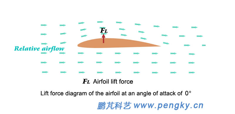
| The cross section of the civil aviation aircraft wing is a common airfoil, which can generate large lift force and has little resistance to airflow. The upper surface of the commonly used aircraft airfoil is curved and the lower surface is straight, see Figure 7, even if the blade and airflow direction. There is also lift force in parallel, because the airflow above the airfoil is much faster than the airflow below. According to the Bernoulli principle of fluid mechanics, the upper gas pressure is smaller than the lower one, and the airfoil is subjected to the upward lift force FL. | |
 |
|
| Figure 7 - Asymmetric airfoil with lift force angle of 0 also has lift force | |
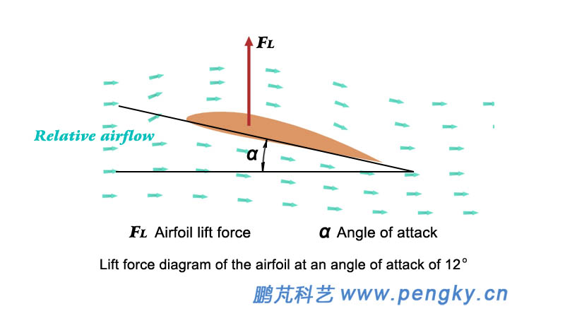
| The angle between the chord of the airfoil and the direction of the incoming flow is called the angle of attack. When the angle of attack increases, the lift force of the airfoil will increase, and the airfoil with the angle of attack can receive greater lift force. Although it increases but is small, the lift force of the airfoil increases as the angle of attack increases as the incoming flow is constant. Figure 8 is a graph of airflow and lift force when the angle of attack is 12 degrees. | |
 |
|
| Figure 8 - Maximum lift force for the airfoil at the right angle of attack | |
The camber airfoil has a lift force of 0 when the angle of attack is a negative value, and the angle of attack is said to be zero lift force angle of attack (zero lift force angle). Although the lift force of the airfoil increases with the increase of the angle of attack, after the angle of attack increases to a certain critical angle, the airflow above the airfoil will separate, resulting in eddy currents, the lift force will drop rapidly, and the resistance will rise sharply. The phenomenon is called stall. This angle is also different for different airfoils, typically 10 to 15 degrees, and is further described below for stalls. The following is an animation of the lift force and drag generated by the airfoil flow. The animation demonstrates the airflow state of the airfoil at zero lift force angle of attack and angle of attack of 0, 6, 12, 18, and 24 degrees. The animation is slightly longer, please wait patiently for the broadcast.
|
|
| Airfoil flow generation generates lift force and resistance animation | |
 |
|
| There are two types of wind turbine for wind power generation: resistance type and lift force type. Horizontal axis wind turbine is basically lift force type. Vertical axis wind turbine has lift force structure and various resistance structures. Wind turbine with high solidity ratio (horizontal or vertical axis) will work in lift force and resistance. | |
| Pressure center | |
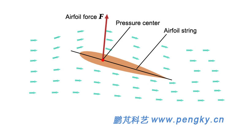
The working airfoil is subjected to the suction pressure of the lower airflow and the suction of the upper airflow. These forces can be expressed by a resultant force, which is the pressure center of the airfoil chord (the line connecting the leading edge and the trailing edge of the airfoil). When the symmetrical airfoil is operated without stalling, the pressure center is at the 1/4 blade chord position from the leading edge of the blade (see Figure 9). |
|
 |
|
| Figure 9 - Airfoil pressure center | |
The asymmetric airfoil is operated at a non-stall state. At a large angle of attack, the pressure center is at a 1/4 blade chord position from the leading edge of the blade. At a small angle of attack, the pressure center moves backward along the chord length of the blade. |
|
| Reynolds' number | |
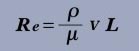
| The Reynolds number is a dimensionless parameter that measures the relative magnitude of the inertial force and the viscous force acting on the fluid. The Reynolds number is represented by Re. | |
 |
|
Where ρ - fluid density; V - characteristic velocity in the flow field; L - characteristic length; μ - viscosity of the fluid. |
|
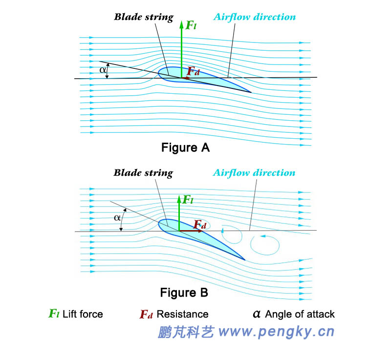
| Stall angle of attack | |
| When the airfoil runs at a small angle of attack, the airfoil is in a normal lift force state, and the airflow above and below the airfoil is smooth and the airfoil surface flows through, as shown in Figure A in Figure 10, which has a larger lift force and resistance is small. If the angle of attack of the wing is increased, when the critical angle is exceeded, the airflow on the upper surface of the airfoil will be separated, and the surface of the airfoil will no longer flow. The vortex will flow above the airfoil, causing the resistance to rise sharply and the lift force to drop. This situation is called stall. See Figure B in Figure 10 for an airflow animation of the airfoil stall in the rear part of the lift force and drag animation generated by the airfoil. | |
 |
|
Figure 10 - The angle of attack exceeds the stall angle of attack and stalls |
|
The critical angle at which the transition occurs is called the critical angle of attack or the stall angle of attack. The stall angle of attack for different airfoil stalls is also different. The normal airfoil is usually between 10 and 15 degrees. Generally, the thin airfoil stalls have a slightly smaller stall angle of attack. The type of stall angle of attack is larger; for the same airfoil, stall angle of attack of the stall is the Reynolds number and the smoothness of the fin when the fin is running. |
|
Wind energy and wind-power utilization coefficient |
|
| Wind energy is the velocity energy of air movement. When the wind speed is v, the kinetic energy of the air flow passing through the area S is | |
| |
|
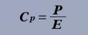
Since it is kinetic energy per second, E is also the power, called wind power. For example, an air flow with a wind speed of 6 m/s has a power of 129.6 W through 1 square meter. |
|
 |
|
The wind-power utilization coefficient is also called the power coefficient. For more information about the wind-power utilization coefficient, see the Wind Energy and Wind Power chapters. |
|
| Betz limit | |
Wind energy is the velocity energy of air movement. When the wind passes through the wind rotor, it pushes the wind rotor to rotate, transforming its velocity energy into the energy of the wind rotor rotation. However, after the wind turbine wind rotor works, the wind speed will not be zero, only decrease. Therefore, the wind only transfers part of the energy to the wind rotor. Then how much energy can the wind transfer to the wind rotor? In 1927, the German Bates theoretically calculated the maximum value of 59.3%. If the wind speed in front of the wind rotor is v, the wind speed through the wind rotor is calculated to be 2v/3. The wind speed away from the position by the wind rotor is 1v/3. 59.3% is called the Bates limit, which is the maximum value of wind-power utilization coefficient of wind turbine. At present, the wind-power utilization coefficient of high performance wind turbine is generally 40% to 45%. |
|
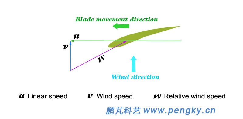
| Relative wind speed | |
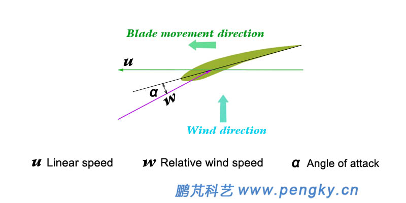
The wind speed felt by the wind turbine blade is the resultant speed of the actual wind speed and the blade moving speed, which is called the relative wind speed. Figure 11 is a blade section of a wind turbine. When the blade moves, the relative wind speed experienced by the blade is w→, which is the resultant vector of the linear velocity (vector) u→ of the blade and the velocity (vector) v→ before the wind enters the rotor. |
|
| w→=u→+v→ | |
 |
|
|
|
The angle between the relative wind speed and the blade string is the angle of attack α of the blade, see Figure 12. |
|
 |
|
| Figure 12 - Relative wind speed and angle of attack | |
| Tip speed ratio | |
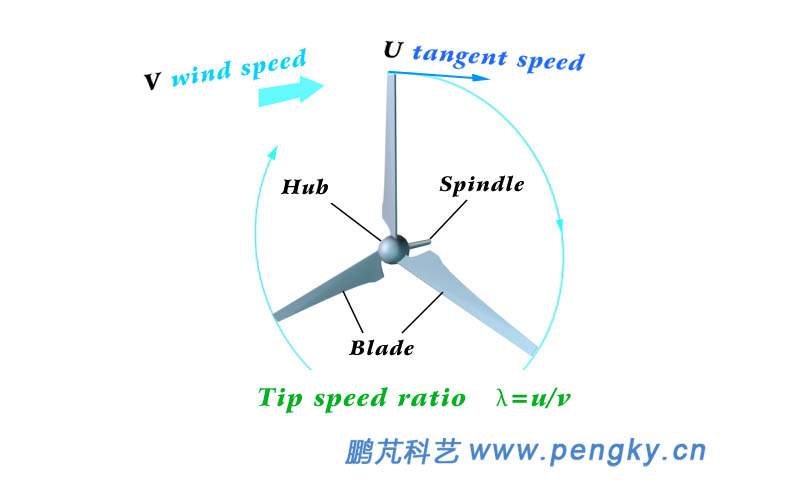
The ratio of the tip speed of the wind rotor blade to the wind speed is called the tip speed ratio. Figure 13 is the rotor of wind turbine, u is the tangential speed of the outer diameter of the rotating wind turbine, v is the speed before the wind enters the rotor, v is vertical to the plane of the wind rotor, and the tip speed ratio is λ |
|
| λ=u/v | |
 |
|
| Figure 13 - Tip speed ratio | |
The tip speed ratio of the resistance wind turbine is generally 0.3 to 0.6, and the tip speed ratio of the lift force type wind turbine is generally 3 to 8. In the lift force type wind turbine, the tip speed ratio directly reflects the angle between the relative wind speed and the direction of the blade movement, which is directly related to the angle of attack of the blade, and is an important parameter for analyzing the performance of the wind turbine. |
|
| Solidity ratio | |
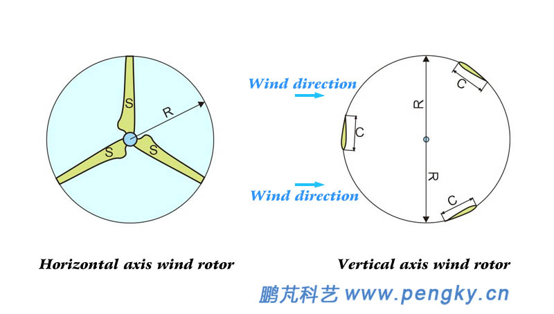
The ratio of the total area of the wind turbine blade to the area of the wind passing through the wind rotor (the swept area of the wind rotor) is called the solidity ratio (volume ratio), and is a reference data for the wind turbine. Figure 14 is the horizontal axis wind rotor, S is the projected area of each blade against the wind, B is the number of blades, R is the radius of the wind rotor, and σ is the solidity ratio. |
|
| |
|
 |
|
| Figure 14 - Wind Rotor Solidity | |
| Figure 14 is a lift-type vertical axis wind rotor, C is the blade chord length, B is the number of blades, R is the rotor radius, L is the blade length, and σ is the solidity ratio. At present, there are two algorithms for the sweeping area of the vertical axis wind rotor, one is considered to be the windward area of the wind rotor, and for the H-type wind rotor, 2RL, then | |
| |
|
| The other is considered to be the product of the circumference of the blade running and the length of the blade, 2RπL, then | |
| σ=BCL/2RπL= BC/2Rπ | |
| In order to simplify the current data, it is directly considered that | |
The multi-blade wind turbine has a high solid ratio and is suitable for wind turbine with low wind speed and low speed and high torque, and its efficiency is low. The low solidity ratio wind turbine with small and narrow blades is more used, which can be operated at a higher speed and has higher efficiency. For more information on the solidity of wind rotor, see the chapter " Rotor Solidity " and the " The Solidity of the Vertical Axis Wind Turbine ". |
|
| Back to Previous Page |
