
|
|
In the alternator principle courseware, the magnetic field of the model is immobile, and the coil rotates in the magnetic field to generate an induced potential. The coil does not do motivation in the actual generator while generating induced potential. The magnetic field is generated by a rotatable magnet with two magnetic poles at the two ends, and also as the rotor of the generator, meanwhile the coil is on the periphery of the magnet and is in the same plane as the magnet shaft. A rotating magnetic field is generated when the magnet rotates, and the coil cuts the magnetic lines of force to generate an induced electromotive force, seeing figure 1. |
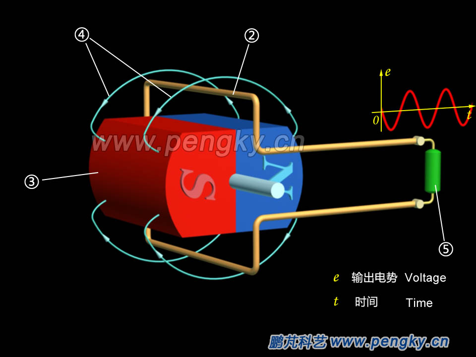 |
| ② Copper Wire loop ③ Permanent magnet rotor ④ Magnetic force line ⑤ Load resistance |
| Figure 1—Alternator model in rotating magnetic field |
| Since the magnetic permeability of the air is too low, the ring-shaped iron core as the stator, can greatly enhance the magnetic induction strength of the magnet in the surrounding of the rotating magnet. There is a pair of slots in the inner circumference of the stator core, and the coil is embedded in the slot. In order to see the relationship between the coil current and the rotor motion, the stator is made translucent. When the magnet rotates, the coil cuts the magnetic lines to induce an alternating current, as shown in figure 2. |
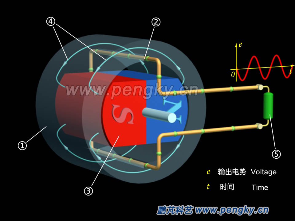
| ① Stator core ② Copper Wire loop ③ Permanent magnet rotor ④Magnetic force line ⑤ Load resistance |
| Figure 2-- Alternator model in rotating magnetic field |
The rotor of a real generator is an electromagnet, meanwhile an exciting coil is wound around the rotor, and a magnetic field is generated by supplying power to the exciting coil through the slip ring. Mount the stator and coil on the periphery of the rotor, and a single-phase alternator model is formed, as shown in figure 3. |
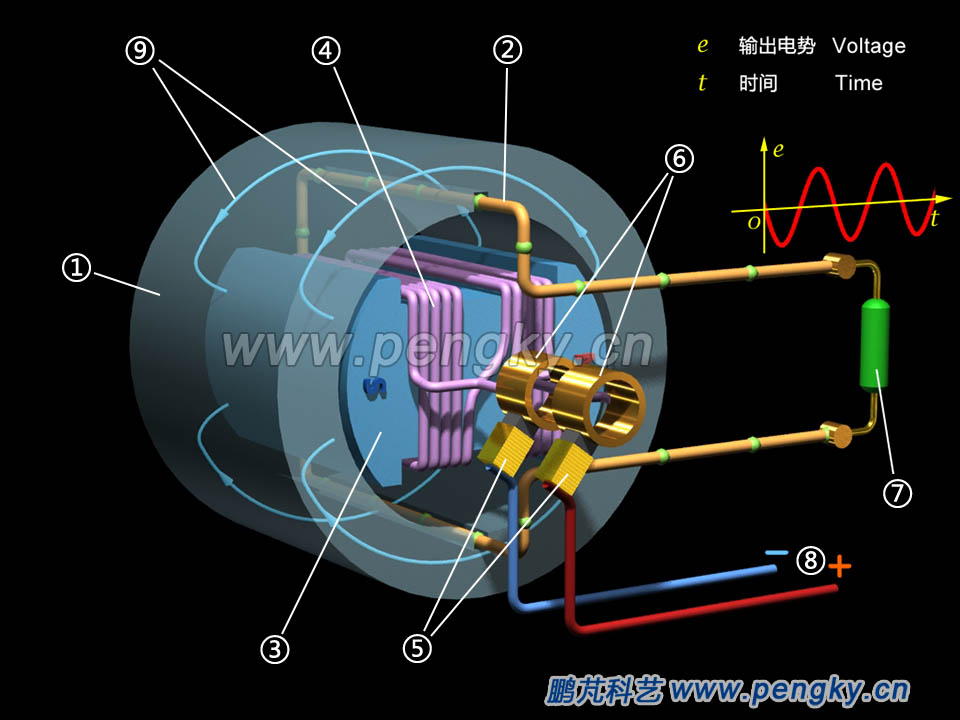
| ① Stator core ② Stator winding ③ Rotor core ④ Excitation winding ⑤ Brush ⑥ Slip rings ⑦ Load resistance ⑧ Excitation power supply ⑨ Lines of flux |
| Figure 3-- Alternator model in rotating magnetic field |
When the rotor rotates on a constant speed, the coil induces an alternating current. The direction of the green ball movement in the figure indicates the direction of the induced current and the speed of the motion indicates the magnitude of the induced current. In this model, the frequency of the induced voltage is exactly the same as the rotor speed. The induced voltage change corresponds exactly to the rotor rotation. When the speed is 50 rpm (50 r/s) or 3000 rpm (3000 rpm), the frequency of the alternating current is 50 Hz. Since the stator winding has only one wire frame, only single-phase AC can be emitted. For the three-phase alternator, please go to the three-phase alternator principle model courseware. This rotating magnetic field generator is called a rotating magnetic pole synchronous generator. In the following animation, we will introduce the rotating armature model and introduce the model of the rotating magnetic synchronous generator. Please watch the 3D animation of the working principle of the rotating magnetic pole synchronous generator. |
| Back to Previous Page |
